Introduction to Crystallography and Mineral Crystal Systems
Crystallography is a fascinating division of the entire
study of mineralogy. Even the non-collector may have an appreciation for
large well-developed beautifully symmetrical individual crystals, like
those of pyrite from Spain, and groups of crystals, such as quartz from
Arkansas or tourmaline from California, because they are esthetically pleasing.
To think that such crystals come from the ground "as is" is surprising
to many. The lay person simply hasn't had the opportunity to learn about
crystals and why they are the way they are; however, neither have many
rockhounds and hobbyists.
We hope to bring you to a greater appreciation of natural mineral crystals
and their forms by giving you some background and understanding into the
world of crystallography. CRYSTALLOGRAPHY is simply a fancy word
meaning "the study of crystals". At one time the word crystal
referred only to quartz crystal, but has taken on a broader definition
which includes all minerals with well expressed crystal shapes.
Crystallography may be studied on many levels, but no matter how elementary
or in-depth a discussion of the topic we have, we confront some geometry.
Oh no, a nasty 8-letter word! Solid geometry, no less. But stop and think
about it, you use geometry every day, whether you hang sheetrock, pour
concrete, deliver the mail, or work on a computer. You just don't think
of it as geometry. Geometry simply deals with spatial relationships. Those
relationships you are familiar with are not intimidating. The key word
here is "familiar". We want this series of articles to help you
become more familiar, and, therefore more comfortable, with the geometry
involved with the study of crystal forms.
Crystallography is easily divided into 3 sections -- geometrical, physical,
and chemical. The latter two involve the relationships of the crystal form
(geometrical) upon the physical and chemical properties of any given mineral.
We will cover the most significant geometric aspects of crystallography
and leave the other topics for later. We do not intend for this series
to be a replacement for a mineralogy textbook, but instead an introduction
to the study of crystallography. During and after reading these articles,
you will probably want to examine one or two textbooks for more detail
about individual subjects. I recommend two: Klein and Hurlbut's Manual
of Mineralogy (20th edition, 1985) and Ford's Textbook of Mineralogy
(4th edition, 1932). Both of these are based on E. S. Dana's earlier classic
publications.
In any type of study, there exists special words used to summarize entire
concepts. This is the special language of the "expert", whether
you speak of electrical engineering, computer science, accounting, or crystallography.
There's no real way to get around learning some of these basic definitions
and "laws" so we might as well jump right into them. Get
Ready!
First, let's define what we're dealing with. A CRYSTAL is a regular
polyhedral form, bounded by smooth faces, which is assumed by a chemical
compound, due to the action of its interatomic forces, when passing, under
suitable conditions, from the state of a liquid or gas to that of a solid.
WOW, what a mouthful! Let's dissect that statement. A polyhedral form simply
means a solid bounded by flat planes (we call these flat planes CRYSTAL
FACES). "A chemical compound" tells us that all minerals
are chemicals, just formed by and found in nature. The last half of the
definition tells us that a crystal normally forms during the change of
matter from liquid or gas to the solid state. In the liquid and gaseous
state of any compound, the atomic forces that bind the mass together in
the solid state are not present. Therefore, we must first crystallize the
compound before we can study it's geometry. Liquids and gases take on the
shape of their container, solids take on one of several regular geometric
forms. These forms may be subdivided, using geometry, into six systems.
But before we can begin to discuss the individual systems and their
variations, let's address several other topics which we will use to describe
the crystal systems. There's also some laws and rules we must learn.
Way back in 1669, Nicholas Steno, a Danish physician and natural scientist,
discovered one of these laws. By examination of numerous specimens of the
same mineral, he found that, when measured at the same temperature, the
angles between similar crystal faces remain constant regardless of the
size or the shape of the crystal. So whether the crystal grew under ideal
conditions or not, if you compare the angles between corresponding faces
on various crystals of the same mineral, the angle remains the same.
Although he did not know why this was true (x-rays had not yet been
discovered, much less x-ray diffraction invented), we now know that this
is so because studies of the atomic structure of any mineral proves that
the structure remains within a close set of given limits or geometric relationships.
If it doesn't, then by the modern definition of a mineral, we are not comparing
the same two minerals. We might be comparing polymorphs, but certainly
not the same mineral! (Polymorphs being minerals with the same chemistry,
like diamond and graphite or sphalerite and wurtzite, but having differing
atomic structure and, therefore, crystallizing in different crystal systems)
Steno's law is called the CONSTANCY OF INTERFACIAL ANGLES and, like
other laws of physics and chemistry, we just can't get away from it.
Now, some of you may be thinking: I have a mineral crystal that does
not match the pictures in the mineral books. What you may have is a distorted
crystal form where some faces may be extremely subordinate or even missing.
Distorted crystals are common and result from less-than-ideal growth conditions
or even breakage and recrystallization of the mineral. However, remember
that we must also be comparing the angles between similar faces. If the
faces are not present, then you cannot compare them. With many crystals
we are dealing with a final shape determined by forces other than those
of the interatomic bonding.
During the process of crystallization in the proper environment, crystals
assume various geometric shapes dependent on the ordering of their atomic
structure and the physical and chemical conditions under which they grow.
If there is a predominant direction or plane in which the mineral forms,
different habits prevail. Thus, galena often forms equate shapes (cubes
or octahedrons), quartz typically is prismatic, and barite tabular.
To discuss the six crystal systems, we have to establish some understanding
of solid geometry. To do this, we will define and describe what are called
CRYSTALLOGRAPHIC AXES. Since we are dealing with 3 dimensions, we
must have 3 axes and, for the initial discussion, let's make them all
equal and at right angles to each other. This is the simplest case
to consider. The axes pass through the center of the crystal and, by using
them, we can describe the intersection of any given face with these 3 axes.
Mineralogists had to decide what to call each of these axes and what
their orientation in each crystal was so that everyone was talking the
same language. Many different systems arose in the early literature. Then,
as certain systems were found to have problems, some were abandoned until
we arrived at the notational system used today. There exists two of these
presently in use, complimentary to each other. One uses number notation
to indicate forms or individual faces and the other uses letters to indicate
forms. But let's get back to our 3 axes and we'll discuss these two systems
later.
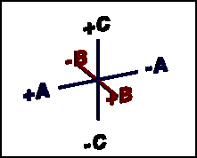
We are going to draw each axis on a sheet of paper and describe its
orientation. All you need for this exercise is a pencil and paper. Make
the first axis vertical, and we'll call it the c axis. The top is the +
end and the bottom is the - end. The second axis, the b axis, is horizontal
and passes through the center of the c axis. It is the same length as the
c axis. The right end is the +, and the left is the -. The third axis is
the a axis and passes at a right angle through the join of the b and c
axes.
It
is somewhat tricky to draw because, even though the a axis is the same
length as the c and b axes, because it goes from front to back it appears
shorter. It is hard to represent a 3-dimensional figure on the 2-dimensional
surface of paper, but you can do it. You have to use a sense of perspective,
as an artist would say. The front end of a, which appears to come out of
the paper, is the + and the back end the - (appears to be in the background
or behind the paper).
This all sounds complicated, but look at Figure 1 if you are having
problems with drawing the final axis. We always refer to the axes in the
order - a, b, c in any type of notation. The point of intersection of the
three axes is called the AXIAL CROSS.
Perspective is a key to drawing 3 dimensional objects on a flat 2D piece
of paper. Perspective is what makes railroad tracks look like they come
together in the distance. It is also what causes optical illusions when
trying to draw axial crosses, or line drawings of crystal models. Perhaps
you've looked at these lines and tried to decide which one comes forward,
and which one recedes, and then have the illusion flip-flop so that it
looks the other way. That's why they are labeled + and -. It can be confusing,
so don't feel like the lone ranger.
We have now reached the point in our discussion that we can actually
mention the six large groups or crystal systems that all crystal forms
may be placed in. We will use our crystallographic axes which we just discussed
to subdivide all known minerals into these systems. The systems are:
(1) CUBIC
(aka ISOMETRIC) - The three crystallographic
axes are all equal in length and intersect at right angles (90 degrees)
to each other. This is exactly what you drew to obtain Figure 1. However,
we now will rename the axes a1, a2, and a3 because they are the same length
(a becomes a1, b becomes a2, and c becomes a3).
(2) TETRAGONAL
- Three axes, all at right angles, two of which are equal in length (a
and b) and one (c) which is different in length (shorter or longer). Note:
If c was equal in length to a or b, then we would be in the cubic system!
Discussed in part 4.
(3) ORTHORHOMBIC
- Three axes, all at right angles, and all three of different lengths.
Note: If any axis was of equal length to any other, then we would be in
the tetragonal system! Discussed in part 5.
(4) HEXAGONAL - Four axes! We must
define this situation since it can not be derived from our Figure 1. Three
of the axes fall in the same plane and intersect at the axial cross at
120 degrees between the positive ends. These 3 axes, labeled a1, a2, and
a3, are the same length. The fourth axis, termed c, may be longer or shorter
than the a axes set. The c axis also passes through the intersection of
the a axes set at right angle to the plane formed by the a set. Look at
Figure 2 to see these relationships more clearly. Discussed in part 6.
(5) MONOCLINIC
- Three axes, all unequal in length, two of which (a and c) intersect at
an oblique angle (not 90 degrees), the third axis (b) is perpendicular
to the other two axes. Note: If a and c crossed at 90 degrees, then we
would be in the orthorhombic system! Discussed in part 7.
(6) TRICLINIC - The
three axes are all unequal in length and intersect at three different angles
(any angle but 90 degrees). Note: If any two axes crossed at 90 degrees,
then we would be describing a monoclinic crystal! Discussed in part 8.
As was stated earlier, all known crystal forms fit into the above six
crystal systems. But why don't all crystals in a given set look the same?
Or, stated differently, why can't I learn six crystal shapes and know all
I need to know? Well, crystals, even of the same mineral, have differing
CRYSTAL FORMS, depending upon their conditions of growth. Whether
they grew rapidly or slowly, under constant or fluctuating conditions of
temperature and pressure, or from highly variable or remarkably uniform
fluids or melts, all these factors have their influence on the resultant
crystal shapes, even when not considering other controls.
We must touch on a type of notation often seen in mineral literature
known as Miller Indices. Before William H. Miller (1801-1880) devised
this mathematical system for describing any crystal face or group of similar
faces (forms), there existed a considerable amount of confusion due to
the many different descriptive systems. Some of these systems used letter
symbols to denote crystal faces and forms. Also different mineralogical
"schools" existed as to how a given crystal should be viewed
or oriented before assigning the crystallographic axes and then describing
the various faces and forms present. If you were of the German school,
you had one view; from the English school another thought; from the French
school, still another opinion.
So the problem was really one of how to bring order to the literature's
chaos. To the problem, Miller (University of Cambridge) applied relatively
simple mathematics - the Universal Language. To the lettering systems,
Miller described the a,b,c (for hexagonal crystals his notation is four
numbers long) intercepts of each planar crystal form as numbers and also
made note of the form letter. His numbering system became widely accepted
and is known as Miller indices. The numbers are presented as whole numbers
(fractions are not allowed) and are the reciprocal of the actual intercept
number, all whole numbers being reduced by their lowest common denominator.
Here's a couple of simple examples from the cubic system.
Let us first describe a face of an octahedron and later
a cube using Miller's indices. First, we should realize that an octahedron
is an eight-sided crystal form that is the simple repetition of an equilateral
triangle about our 3 crystallographic axes. The triangle is oriented so
that it crosses the a1, a2, and a3 axes all at the same distance from the
axial cross. This unit distance is given as 1. Dividing 1 into the whole
number 1 (it's a reciprocal, remember?) yields a value of 1 for each Miller
number. So the Miller indices is (111) for the face that intercepts the
positive end of each of the 3 axes. See Figure 3 for all possible numbers
for the 8 faces. Note: A bar over the number tells me that the intercept
was across the negative end of the particular crystallographic axis. The
octahedral form is given the letter designation of "o".
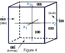
Now to the cube face. A cube face that intercepts the a3
(vertical) axis on the + end will not intercept the a1 and a2 axes. If
the face does not intercept an axis, then we assign a mathematical value
of infinity to it. So we start with Infinity, Infinity, 1 (a1, a2, a3).
Infinity divided into 0 = 0 (any number divided into zero equals zero).
So the Miller indices of the +a3 intercept face equals (001). See the drawing
for all possible Miller indices for the 6 faces of a cube (Figure 4).
I think we should briefly mention cleavage at this point. CLEAVAGE
is the preferred planar direction of breakage that many minerals possess.
It is due to planes of weakness that exist in some minerals because the
bonding strength between the atoms or molecules is not the same in every
direction. Because crystals are composed of orderly arrangements of atoms
or molecules, we really should expect cleavage to be present in many crystals.
The notation that denotes cleavage is derived in much the same manner as
Miller indices, but is expressed in braces. So a cubic crystal, say diamond,
no matter whether it exhibits cubic {001} or octahedral {111} crystal form,
has an octahedral cleavage form that is given as {111}.
Note: The Miller indices when used as face symbols are enclosed in parentheses,
as the (111) face for example. Form symbols are enclosed in braces, as
the {111} form for example. Zone symbols are enclosed in brackets, [111]
for example and denote a zone axis in the crystal. So in the discussion
of cleavage (above), you must use braces to denote cleavage. Cleavage is
analogous to form as cubic, octahedral, or pinacoidal cleavage and does
not refer to just one face of a form.
Now we are ready to discuss ELEMENTS OF SYMMETRY. These include
PLANES OF SYMMETRY, AXES OF SYMMETRY, and CENTER OF SYMMETRY.
These symmetry elements may be or may not be combined in the same crystal.
Indeed, we will find that one crystal class or system has only one of these
elements!
Huh? These parts, when put together, make the planes in figure 6.
Any two dimensional surface (we can call it flat) that, when passed
through the center of the crystal, divides it into two symmetrical parts
that are MIRROR IMAGES is a PLANE OF SYMMETRY. I repeat:
any plane of symmetry divides the crystal form into two mirror images.
Planes of symmetry are often referred to as mirror image planes. Let's
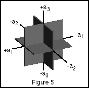
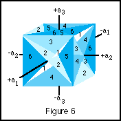
discuss a cube again. A cube has 9 planes of symmetry, 3 of one set and
6 of another. We must use two figures to easily recognize all of them.
In Figure 5 the planes of symmetry are parallel to the faces of the
cube form, in Figure 6 the planes of symmetry join the opposite cube edges.
The second set corresponds to the octahedral crystal form. Planes of symmetry
are always possible crystal forms. This means that, although not
always present on many natural crystals, there exists the possibility that
other crystal faces may be expressed. So even though a cube form does not
present an octahedral face, it is always possible that it could have formed
under the right conditions.
The
typical human has two hands, right and left. Place them together palms
facing away from you and the tips of the thumbs touching. Assuming that
you have the same number of fingers on each hand, you will note that your
right hand is the mirror image of your left and vise versa. The average
person is symmetrical, having binary symmetry vertically from the head
to the feet when viewed from the front or back (bilateral symmetry).
You can have a lot of laughs with friends and a long mirror using this
symmetry element. You need at least one other person to do this so you
both can view the results! Using Figures 5 and 6 as guides, take a wood
or plastic cube and see if you can draw with a marker all the planes of
symmetry that are present. Refer to the two figures for help.
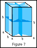
It is sometimes convenient to designate planes of symmetry as axial,
diagonal, principle, or intermediate. Figure 7 is an example of the 5 planes
of symmetry of the tetragonal system and the proper abbreviated notation.
AXES OF SYMMETRY can be rather confusing at first, but let's
have a go at them anyway. Any line through the center of the crystal around
which the crystal may be rotated so that after a definite angular revolution
the crystal form appears the same as before is termed an axis of symmetry.
Depending on the amount or degrees of rotation necessary, four types of
axes of symmetry are possible when you are considering crystallography
(some textbooks list five). Given below are all possible rotational axes:
When rotation repeats form every 60 degrees, then we have sixfold or HEXAGONAL
SYMMETRY. A filled hexagon symbol is noted on the rotational axis.
When rotation repeats form every 90 degrees, then we have fourfold or
TETRAGONAL SYMMETRY. A filled square is noted on the rotational
axis.
When rotation repeats form every 120 degrees, then we have threefold
or TRIGONAL SYMMETRY. A filled equilateral triangle is noted on
the rotational axis.
When rotation repeats form every 180 degrees, then we have twofold or
BINARY SYMMETRY. A filled oval is noted on the rotational axis.
When rotation repeats form every 360 degrees, then we use a filled circle
as notation. This one I consider optional to list as almost any object
has this symmetry. If you really want to know the truth, this means NO SYMMETRY!!
Note that rotational axes may be on the plane of the face, on the edge
of where two faces meet, or on the point of conjunction of three or more
faces. On a complete crystal form, the axis must pass through the center
of the crystal and exist at the equivalent site on the opposite side of
the crystal as it entered.
Take a solid cube, made of wood or plastic (a clear plastic cube box
works well for this exercise). Mark, using the rotational notation, every
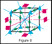
four-, three-, and two-fold axis of rotation that you can find. I think
you will be surprised how many there are! Examine Figure 8 (the cube from
hades!) to see how many symbols you can draw on your cube.
Now I'm sorry that this is not all there is to rotational axes, but there
is another situation that we must consider -- AXES OF ROTARY INVERSION.
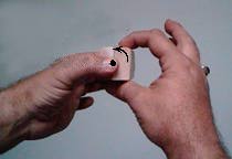
This is where the twisted mind has one up on the rest of us (there's a
pun in there somewhere!). We will consider a couple of simple examples.
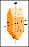
First, let's examine a a crystal as drawn in Figure 9a at left. Use a piece
of "2 by 2" board and make this crystal form by cutting off the
ends so the wood block looks like the drawing. Hold the block in your left
hand with your thumb on the top and in the center of the 2-face edge join
(long axis) and your index finger on the same join on the underside. Your
palm will be toward your body. Align your two fingers so that you are looking
straight down on your thumb and can not see end of your index finger. The
top of the block will appear as 2 equal-sized faces, sloping away from
you. If you rotate the block 180 degrees, the faces will be appear back
in the same position (2-fold axis of rotation), but here's the tricky part
-- rotate the specimen 90 degrees and then turn your wrist where your index
finger is on top (easiest done by turning your wrist counterclockwise).
You will see that the block's faces appear in the original position in
the original position. You have discovered an axis of rotary inversion!
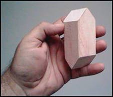
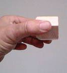
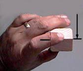
Fig 9b: Wooden or plastic models are known in a mineralogy class as 'idiot blocks'.
Fig 9c:
Fig 9d: Block rotated 90 degrees around the axis shown by the dot
Fig 9e: Block rotated counterclockwise 180 degrees on the axis shown by the arrow.
See the series of photos (Figures 9 b-9 e) if you get confused. Some textbooks
term these axes rotary reflection axes or rotoinversion axes. There may
be 1-, 2-, 3-, 4-, and 6-fold rotary inversion axes present in natural
crystal forms, depending upon the crystal system we are discussing. I refer
you to Klein and Hurlbut's Manual of Mineralogy (after J. S. Dana) if you
want to sharpen your axes of rotary inversion skills. With axes of rotation,
there is a graphical notation used which looks like a very bold type-face
comma. For axes of rotary inversion, the same symbol is used, but appears
dashed.
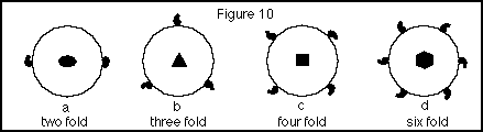
Both types of symmetrical rotational axes (discussed above) are commonly
plotted on a circle (representing the complete cycle of one 360 degree
rotation). The simple axes of rotation symbol for a face is plotted at
the center of the circle and the axes of rotation and rotary inversion
are plotted on the circle's boundary at whatever rotational angle is appropriate.
See Figure 10 for examples.
We have finally come to our last topic of geometric crystallography
-- the CENTER OF SYMMETRY. Most crystals have a center of symmetry,
even though they may not possess either planes of symmetry or axes of symmetry.
Triclinic crystals usually only have a center of symmetry. If you can pass
an imaginary line from the surface of a crystal face through the center
of the crystal (the axial cross) and it intersects a similar point on a
face equidistance from the center, then the crystal has a center of symmetry.
We may discuss this in a little more detail in the article about the triclinic
system.
We now have to consider the relation of geometrical symmetry to CRYSTALLOGRAPHIC
SYMMETRY. The crystal face arrangement symmetry of any given crystal
is simply an expression of the internal atomic structure. This internal
structure is generally alike in any parallel direction. But we must keep
in mind that the relative size of a given face is of no importance, only
the angular relationship or position to other given crystal faces.
Refer back to Steno's law concerning the CONSTANCY OF INTERFACIAL ANGLES.
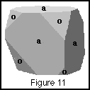
Let's
consider a crystal in the cubic system with both cube {001} and octahedral
{111} forms represented (Figure 11). In our figure, we have used the letter
designation of -a- for the cube faces and -o- for the octahedral faces.
Despite the initial observation that both the various cube and octahedral
faces are unequal in size, the example displays all the symmetry elements
and relationships of a crystal from the cubic system. I hope you now begin
to grasp the difficulty of learning crystallography using natural crystals.
Due to a variety of factors, many natural crystals have some degree of
distortion to their growth, causing the faces to vary in size and sometimes
shape. In college mineralogy, this problem was resolved by requiring the
classroom use of a set of crystal forms, sometimes made of wood or plastic.
These sets were not-so-fondly termed "idiot blocks" by exasperated
students. Once you mastered the various forms and understood symmetry planes,
rotational axes, and form names, then you became recognized as a "complete
idiot" and could go on to examine real minerals!
Depending upon what elements of symmetry are present, all crystals may
be divided into 32 distinct groups called CLASSES OF SYMMETRY. Remember,
we concern ourselves with the symmetry elements we learned above, not the
malformed crystal shapes of most minerals. Only forms which belong to the
same class can occur in combination together in nature. We can not find
a cube face on a hexagonal crystal. Likewise, we will never discover the
rhombic dipyramid termination of a hexagonal crystal on a tetragonal crystal.
So our laws, rules, and symmetry elements previously discussed prevent
chaos in our beautifully symmetrical world of crystallography. Certainly,
when dealing with real crystals, distortion problems can arise! Think of
capillary pyrite. Here you have a cubic crystal which, due to a growth
phenomenon, has one axis nearing infinity in length in relation to the
other two. But this is caused by special conditions during growth, not
the crystallography.
There are graphical methods of plotting all possible crystal faces and
symmetry elements on a type of diagram called a stereo net. Stereo nets
give a way to represent three-dimensional data on a two-dimensional surface
(a flat sheet of paper). A discussion of stereo nets is out of the scope
of this paper because to present it adequately would require much graphing,
mathematics, and that each reader possess stereo-net paper. If you wish
to attempt any exercises with stereo nets, I refer you to the previously
mentioned textbooks. You can purchase the graph paper at most major college
and university bookstores.
Well, if your faces are all shining, your symmetry now in order, and
your axes properly aligned, then stay tuned for the next article when we
consider crystal forms and the 32 symmetry classes. Then we will have the
background necessary to discuss the six crystal systems!
 It
is somewhat tricky to draw because, even though the a axis is the same
length as the c and b axes, because it goes from front to back it appears
shorter. It is hard to represent a 3-dimensional figure on the 2-dimensional
surface of paper, but you can do it. You have to use a sense of perspective,
as an artist would say. The front end of a, which appears to come out of
the paper, is the + and the back end the - (appears to be in the background
or behind the paper).
It
is somewhat tricky to draw because, even though the a axis is the same
length as the c and b axes, because it goes from front to back it appears
shorter. It is hard to represent a 3-dimensional figure on the 2-dimensional
surface of paper, but you can do it. You have to use a sense of perspective,
as an artist would say. The front end of a, which appears to come out of
the paper, is the + and the back end the - (appears to be in the background
or behind the paper).
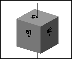 (1) CUBIC
(aka ISOMETRIC) - The three crystallographic
axes are all equal in length and intersect at right angles (90 degrees)
to each other. This is exactly what you drew to obtain Figure 1. However,
we now will rename the axes a1, a2, and a3 because they are the same length
(a becomes a1, b becomes a2, and c becomes a3).
(1) CUBIC
(aka ISOMETRIC) - The three crystallographic
axes are all equal in length and intersect at right angles (90 degrees)
to each other. This is exactly what you drew to obtain Figure 1. However,
we now will rename the axes a1, a2, and a3 because they are the same length
(a becomes a1, b becomes a2, and c becomes a3).
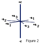 (4) HEXAGONAL - Four axes! We must
define this situation since it can not be derived from our Figure 1. Three
of the axes fall in the same plane and intersect at the axial cross at
120 degrees between the positive ends. These 3 axes, labeled a1, a2, and
a3, are the same length. The fourth axis, termed c, may be longer or shorter
than the a axes set. The c axis also passes through the intersection of
the a axes set at right angle to the plane formed by the a set. Look at
Figure 2 to see these relationships more clearly. Discussed in part 6.
(4) HEXAGONAL - Four axes! We must
define this situation since it can not be derived from our Figure 1. Three
of the axes fall in the same plane and intersect at the axial cross at
120 degrees between the positive ends. These 3 axes, labeled a1, a2, and
a3, are the same length. The fourth axis, termed c, may be longer or shorter
than the a axes set. The c axis also passes through the intersection of
the a axes set at right angle to the plane formed by the a set. Look at
Figure 2 to see these relationships more clearly. Discussed in part 6.
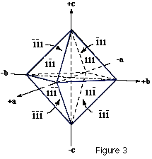 Let us first describe a face of an octahedron and later
a cube using Miller's indices. First, we should realize that an octahedron
is an eight-sided crystal form that is the simple repetition of an equilateral
triangle about our 3 crystallographic axes. The triangle is oriented so
that it crosses the a1, a2, and a3 axes all at the same distance from the
axial cross. This unit distance is given as 1. Dividing 1 into the whole
number 1 (it's a reciprocal, remember?) yields a value of 1 for each Miller
number. So the Miller indices is (111) for the face that intercepts the
positive end of each of the 3 axes. See Figure 3 for all possible numbers
for the 8 faces. Note: A bar over the number tells me that the intercept
was across the negative end of the particular crystallographic axis. The
octahedral form is given the letter designation of "o".
Let us first describe a face of an octahedron and later
a cube using Miller's indices. First, we should realize that an octahedron
is an eight-sided crystal form that is the simple repetition of an equilateral
triangle about our 3 crystallographic axes. The triangle is oriented so
that it crosses the a1, a2, and a3 axes all at the same distance from the
axial cross. This unit distance is given as 1. Dividing 1 into the whole
number 1 (it's a reciprocal, remember?) yields a value of 1 for each Miller
number. So the Miller indices is (111) for the face that intercepts the
positive end of each of the 3 axes. See Figure 3 for all possible numbers
for the 8 faces. Note: A bar over the number tells me that the intercept
was across the negative end of the particular crystallographic axis. The
octahedral form is given the letter designation of "o".
 Now to the cube face. A cube face that intercepts the a3
(vertical) axis on the + end will not intercept the a1 and a2 axes. If
the face does not intercept an axis, then we assign a mathematical value
of infinity to it. So we start with Infinity, Infinity, 1 (a1, a2, a3).
Infinity divided into 0 = 0 (any number divided into zero equals zero).
So the Miller indices of the +a3 intercept face equals (001). See the drawing
for all possible Miller indices for the 6 faces of a cube (Figure 4).
Now to the cube face. A cube face that intercepts the a3
(vertical) axis on the + end will not intercept the a1 and a2 axes. If
the face does not intercept an axis, then we assign a mathematical value
of infinity to it. So we start with Infinity, Infinity, 1 (a1, a2, a3).
Infinity divided into 0 = 0 (any number divided into zero equals zero).
So the Miller indices of the +a3 intercept face equals (001). See the drawing
for all possible Miller indices for the 6 faces of a cube (Figure 4).

 The
typical human has two hands, right and left. Place them together palms
facing away from you and the tips of the thumbs touching. Assuming that
you have the same number of fingers on each hand, you will note that your
right hand is the mirror image of your left and vise versa. The average
person is symmetrical, having binary symmetry vertically from the head
to the feet when viewed from the front or back (bilateral symmetry).
The
typical human has two hands, right and left. Place them together palms
facing away from you and the tips of the thumbs touching. Assuming that
you have the same number of fingers on each hand, you will note that your
right hand is the mirror image of your left and vise versa. The average
person is symmetrical, having binary symmetry vertically from the head
to the feet when viewed from the front or back (bilateral symmetry).
 Note that rotational axes may be on the plane of the face, on the edge
of where two faces meet, or on the point of conjunction of three or more
faces. On a complete crystal form, the axis must pass through the center
of the crystal and exist at the equivalent site on the opposite side of
the crystal as it entered.
Note that rotational axes may be on the plane of the face, on the edge
of where two faces meet, or on the point of conjunction of three or more
faces. On a complete crystal form, the axis must pass through the center
of the crystal and exist at the equivalent site on the opposite side of
the crystal as it entered.
 First, let's examine a a crystal as drawn in Figure 9a at left. Use a piece
of "2 by 2" board and make this crystal form by cutting off the
ends so the wood block looks like the drawing. Hold the block in your left
hand with your thumb on the top and in the center of the 2-face edge join
(long axis) and your index finger on the same join on the underside. Your
palm will be toward your body. Align your two fingers so that you are looking
straight down on your thumb and can not see end of your index finger. The
top of the block will appear as 2 equal-sized faces, sloping away from
you. If you rotate the block 180 degrees, the faces will be appear back
in the same position (2-fold axis of rotation), but here's the tricky part
-- rotate the specimen 90 degrees and then turn your wrist where your index
finger is on top (easiest done by turning your wrist counterclockwise).
You will see that the block's faces appear in the original position in
the original position. You have discovered an axis of rotary inversion!
First, let's examine a a crystal as drawn in Figure 9a at left. Use a piece
of "2 by 2" board and make this crystal form by cutting off the
ends so the wood block looks like the drawing. Hold the block in your left
hand with your thumb on the top and in the center of the 2-face edge join
(long axis) and your index finger on the same join on the underside. Your
palm will be toward your body. Align your two fingers so that you are looking
straight down on your thumb and can not see end of your index finger. The
top of the block will appear as 2 equal-sized faces, sloping away from
you. If you rotate the block 180 degrees, the faces will be appear back
in the same position (2-fold axis of rotation), but here's the tricky part
-- rotate the specimen 90 degrees and then turn your wrist where your index
finger is on top (easiest done by turning your wrist counterclockwise).
You will see that the block's faces appear in the original position in
the original position. You have discovered an axis of rotary inversion!
 Let's
consider a crystal in the cubic system with both cube {001} and octahedral
{111} forms represented (Figure 11). In our figure, we have used the letter
designation of -a- for the cube faces and -o- for the octahedral faces.
Despite the initial observation that both the various cube and octahedral
faces are unequal in size, the example displays all the symmetry elements
and relationships of a crystal from the cubic system. I hope you now begin
to grasp the difficulty of learning crystallography using natural crystals.
Due to a variety of factors, many natural crystals have some degree of
distortion to their growth, causing the faces to vary in size and sometimes
shape. In college mineralogy, this problem was resolved by requiring the
classroom use of a set of crystal forms, sometimes made of wood or plastic.
These sets were not-so-fondly termed "idiot blocks" by exasperated
students. Once you mastered the various forms and understood symmetry planes,
rotational axes, and form names, then you became recognized as a "complete
idiot" and could go on to examine real minerals!
Let's
consider a crystal in the cubic system with both cube {001} and octahedral
{111} forms represented (Figure 11). In our figure, we have used the letter
designation of -a- for the cube faces and -o- for the octahedral faces.
Despite the initial observation that both the various cube and octahedral
faces are unequal in size, the example displays all the symmetry elements
and relationships of a crystal from the cubic system. I hope you now begin
to grasp the difficulty of learning crystallography using natural crystals.
Due to a variety of factors, many natural crystals have some degree of
distortion to their growth, causing the faces to vary in size and sometimes
shape. In college mineralogy, this problem was resolved by requiring the
classroom use of a set of crystal forms, sometimes made of wood or plastic.
These sets were not-so-fondly termed "idiot blocks" by exasperated
students. Once you mastered the various forms and understood symmetry planes,
rotational axes, and form names, then you became recognized as a "complete
idiot" and could go on to examine real minerals!